Что такое layout в unity
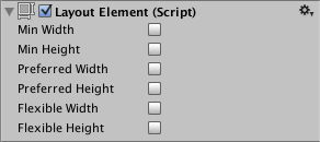
Layout Element
Свойства
| Свойство: | Функция: |
|---|---|
| Min Width | The minimum width this layout element should have. |
| Min Height | The minimum height this layout element should have. |
| Preferred Width | The preferred width this layout element should have before additional available width is allocated. |
| Preferred Height | The preferred height this layout element should have before additional available height is allocated. |
| Flexible Width | The relative amount of additional available width this layout element should fill out relative to its siblings. |
| Flexible Height | The relative amount of additional available height this layout element should fill out relative to its siblings. |
Описание
If you want to override the minimum, preferred, or flexible size of a layout element, you can do that by adding a Layout Element component to the Game Object.
The properties are used in the following manner when a layout controller allocates width or height to a layout element:
The Layout Element component lets you override the values for one or more of the layout properties. Enable the checkbox for a property you want to override and then specify the value you want to override with.
Minimum and preferred sizes are defined in regular units, while the flexible sizes are defined in relative units. If any layout element has flexible size greater than zero, it means that all the available space will be filled out. The relative flexible size values of the siblings determines how big a proportion of the available space each sibling fills out. Most commonly, flexible width and height is set to just 0 or 1.
Specifying both a preferred size and a flexible size can make sense in certain cases. Flexible sizes are only allocated after all preferred sizes have been fully allocated. Thus, a layout element which has a flexible size specified but no preferred size will keep its minimum size until other layout elements have grown to their full preferred size, and only then begin to grow based on additional available space. By also specifying a flexible size, this can be avoided and the element can grow to its preferred size in tandem with the other layout elements that have preferred sizes, and then grow further once all flexible sizes have been allocated.
Layout Element
A layout controller allocates width or height to a layout element in the following order:
For more information about minimum, preferred, and flexible size, see documentation on Auto Layout.
Properties
When you enable a width or height property, a value field appears next to it. Use this value field to enter the exact value for the width or height. Min and Preferred sizes are in regular units, while the Flexible sizes are in relative units.
| Property: | Function: |
|---|---|
| Ignore Layout | When enabled, the layout system ignores this layout element. |
| Min Width | The minimum width this layout element should have. |
| Min Height | The minimum height this layout element should have. |
| Preferred Width | The preferred width this layout element should have before additional available width is allocated. |
| Preferred Height | The preferred height this layout element should have before additional available height is allocated. |
| Flexible Width | The relative amount of additional available width this layout element should fill out relative to its siblings. |
| Flexible Height | The relative amount of additional available height this layout element should fill out relative to its siblings. |
| Layout Priority | The layout priority for this component. If a GameObject has more than one component with layout properties (for example, an Image component and a LayoutElement component), the layout system uses the property values from the component with the highest Layout Priority. If the components have the same Layout Priority, the layout system uses the highest value for each property, regardless of which component it comes from. |
Description
The Layout Element component lets you override the values for one or more of the layout properties. Enable the checkbox for a property you want to override and then specify the value you want to override with.
Minimum and preferred sizes are defined in regular units, while the flexible sizes are defined in relative units. If any layout element has flexible size greater than zero, it means that all the available space will be filled out. The relative flexible size values of the siblings determines how big a proportion of the available space each sibling fills out. Most commonly, flexible width and height is set to just 0 or 1.
Specifying both a preferred size and a flexible size can make sense in certain cases. Flexible sizes are only allocated after all preferred sizes have been fully allocated. Thus, a layout element which has a flexible size specified but no preferred size will keep its minimum size until other layout elements have grown to their full preferred size, and only then begin to grow based on additional available space. By also specifying a flexible size, this can be avoided and the element can grow to its preferred size in tandem with the other layout elements that have preferred sizes, and then grow further once all flexible sizes have been allocated.
Basic Layout
The Rect Tool
Every UI element is represented as a rectangle for layout purposes. This rectangle can be manipulated in the Scene View using the Rect Tool in the toolbar. The Rect Tool is used both for Unity’s 2D features and for UI, and in fact can be used even for 3D objects as well.
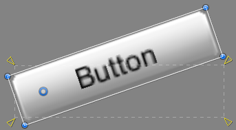
The Rect Tool can be used to move, resize and rotate UI elements. Once you have selected a UI element, you can move it by clicking anywhere inside the rectangle and dragging. You can resize it by clicking on the edges or corners and dragging. The element can be rotated by hovering the cursor slightly away from the corners until the mouse cursor looks like a rotation symbol. You can then click and drag in either direction to rotate.
Just like the other tools, the Rect Tool uses the current pivot mode and space, set in the toolbar. When working with UI it’s usually a good idea to keep those set to Pivot and Local.
Rect Transform
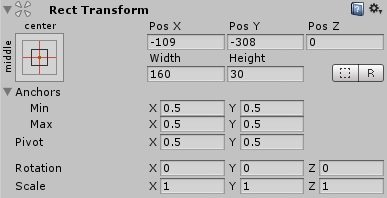
The Rect Transform is a new transform component that is used for all UI elements instead of the regular Transform component.
Rect Transforms have position, rotation, and scale just like regular Transforms, but it also has a width and height, used to specify the dimensions of the rectangle.
Resizing Versus Scaling
When the Rect Tool is used to change the size of an object, normally for Sprites in the 2D system and for 3D objects it will change the local scale of the object. However, when it’s used on an object with a Rect Transform on it, it will instead change the width and the height, keeping the local scale unchanged. This resizing will not affect font sizes, border on sliced images, and so on.
Pivot
Rotations, size, and scale modifications occur around the pivot so the position of the pivot affects the outcome of a rotation, resizing, or scaling. When the toolbar Pivot button is set to Pivot mode, the pivot of a Rect Transform can be moved in the Scene View.
Anchors
Rect Transforms include a layout concept called anchors. Anchors are shown as four small triangular handles in the Scene View and anchor information is also shown in the Inspector.
If the parent of a Rect Transform is also a Rect Transform, the child Rect Transform can be anchored to the parent Rect Transform in various ways. For example, the child can be anchored to the center of the parent, or to one of the corners.
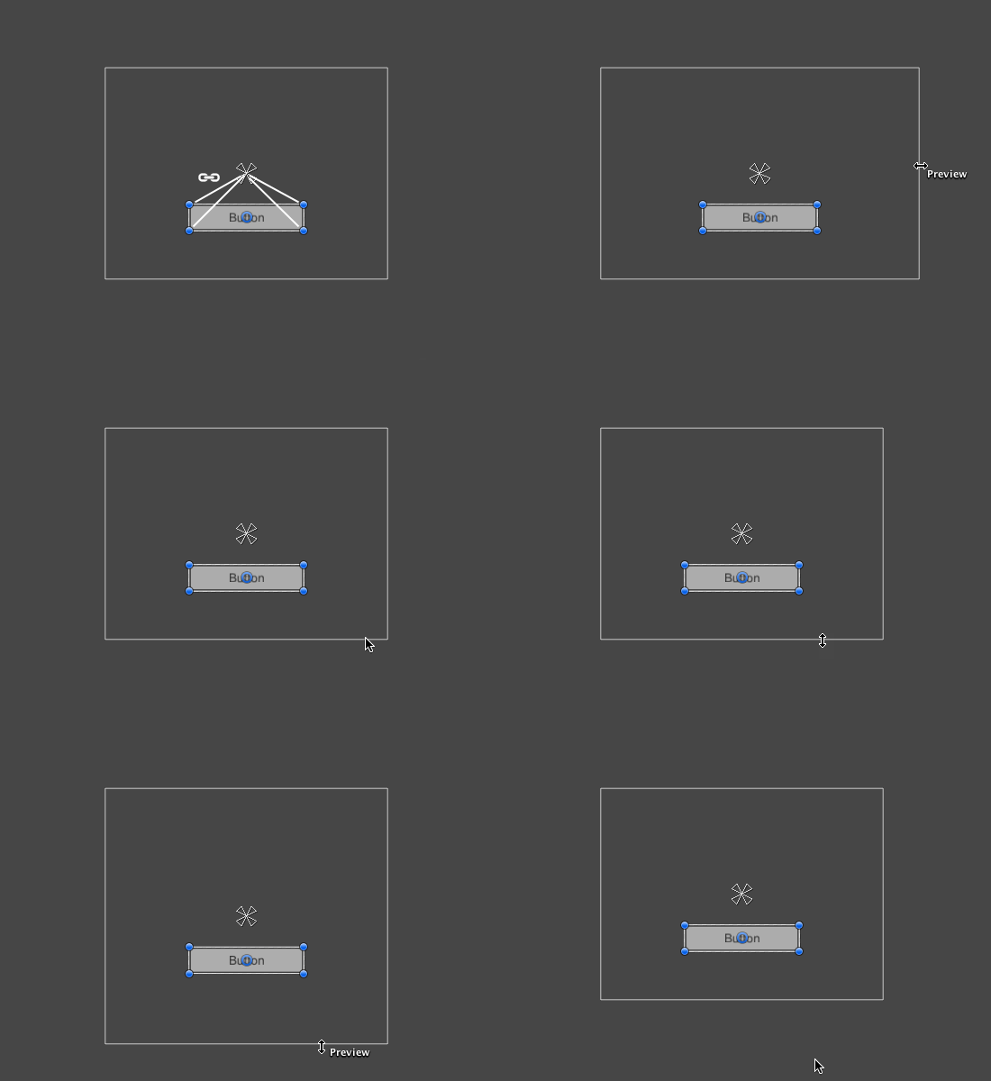
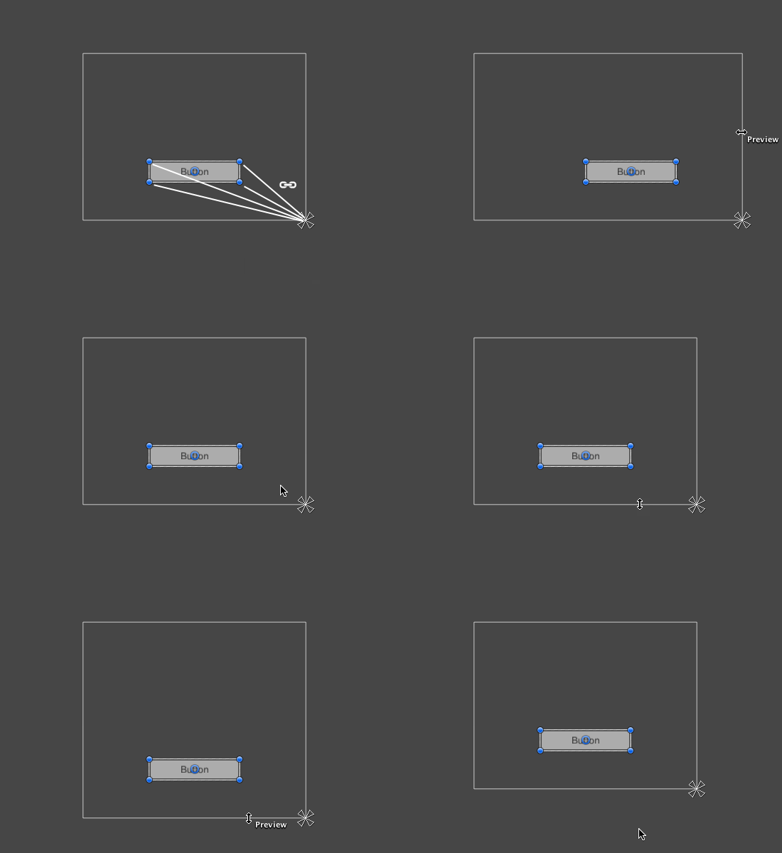
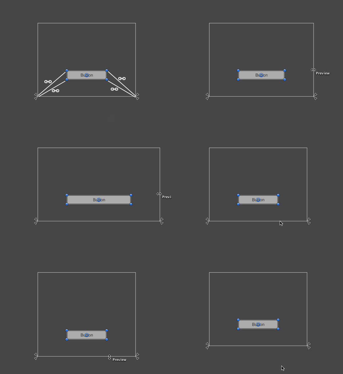
The anchoring also allows the child to stretch together with the width or height of the parent. Each corner of the rectangle has a fixed offset to its corresponding anchor, i.e. the top left corner of the rectangle has a fixed offset to the top left anchor, etc. This way the different corners of the rectangle can be anchored to different points in the parent rectangle.
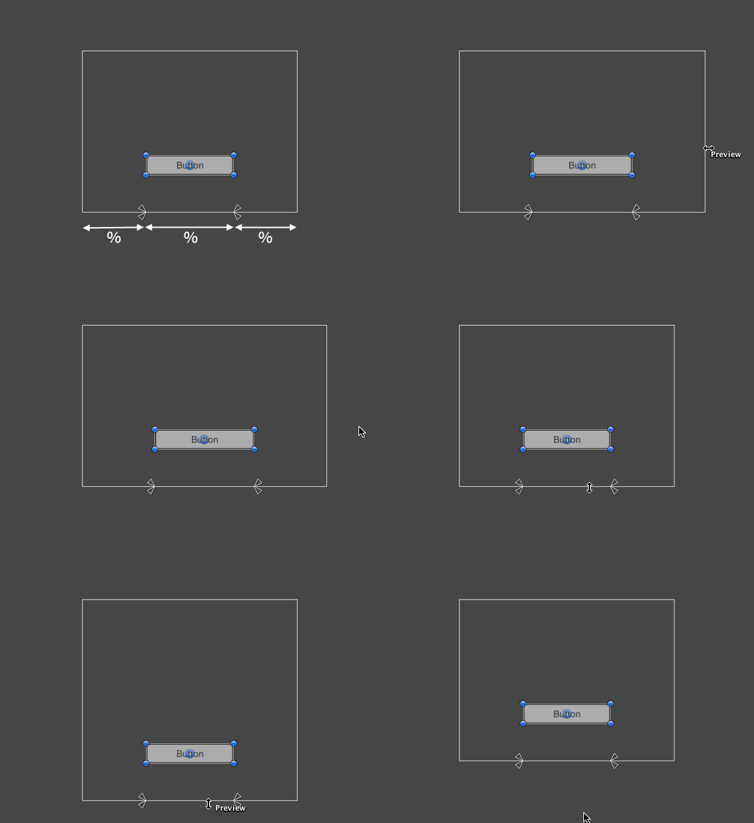
The positions of the anchors are defined in fractions (or percentages) of the parent rectangle width and height. 0.0 (0%) corresponds to the left or bottom side, 0.5 (50%) to the middle, and 1.0 (100%) to the right or top side. But anchors are not limited to the sides and middle; they can be anchored to any point within the parent rectangle.
You can drag each of the anchors individually, or if they are together, you can drag them together by clicking in the middle in between them and dragging. If you hold down Shift key while dragging an anchor, the corresponding corner of the rectangle will move together with the anchor.
A useful feature of the anchor handles is that they automatically snap to the anchors of sibling rectangles to allow for precise positioning.
Anchor presets
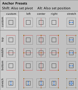
In the Inspector, the Anchor Preset button can be found in the upper left corner of the Rect Transform component. Clicking the button brings up the Anchor Presets dropdown. From here you can quickly select from some of the most common anchoring options. You can anchor the UI element to the sides or middle of the parent, or stretch together with the parent size. The horizontal and vertical anchoring is independent.
The Anchor Presets buttons displays the currently selected preset option if there is one. If the anchors on either the horizontal or vertical axis are set to different positions than any of the presets, the custom options is shown.
Anchor and position fields in the Inspector
You can click the Anchors expansion arrow to reveal the anchor number fields if they are not already visible. Anchor Min corresponds to the lower left anchor handle in the Scene View, and Anchor Max corresponds to the upper right handle.
The position fields of rectangle are shown differently depending on whether the anchors are together (which produces a fixed width and height) or separated (which causes the rectangle to stretch together with the parent rectangle).
When all the anchor handles are together the fields displayed are Pos X, Pos Y, Width and Height. The Pos X and Pos Y values indicate the position of the pivot relative to the anchors.
When the anchors are separated the fields can change partially or completely to Left, Right, Top and Bottom. These fields define the padding inside the rectangle defined by the anchors. The Left and Right fields are used if the anchors are separated horizontally and the Top and Bottom fields are used if they are separated vertically.
Note that changing the values in the anchor or pivot fields will normally counter-adjust the positioning values in order to make the rectangle stay in place. If cases where this is not desired, the Raw Mode can be enabled using a small button in the Inspector. This causes the anchor and pivot value to be able to be changed without any other values changing as a result. This will likely cause the rectangle to be visually moved or resized, since its position and size is dependent on the anchor and pivot values.
Режимы расположения
Фиксированное расположение vs автоматическое расположение
Фиксированное расположение имеет смысл, когда у вас есть заранее подготовленный дизайн, опираясь на который вы можете работать. Автоматическое расположение имеет смысл, когда вы не знаете как много элементов вам понадобится, или если не хотите заниматься расположением каждого контрола вручную. Например, если вы создаёте разные кнопки, количество которых зависит от количества сохранённых игр, вы не знаете в точности как много кнопок придётся отрисовать. В таком случае автоматическое расположение будет очень к месту. Выбор режима расположения сильно зависит от дизайна игры и от того, как вы желаете представлять ваш интерфейс пользователю
Существует два ключевых различия при использовании автоматического расположения:
Выстраивание контролов
В зависимости от используемого режима расположения, существует различные подходы к контролированию позиционирования и группирования контролов. При фиксированном расположении, вы можете поместить разные контролы в группы ( Groups ). При автоматическом расположении, вы можете разместить различные контролы в областях ( Areas ), горизонтальных группах ( Horizontal Groups ) и вертикальных группах ( Vertical Groups ).
Например, очень просто центрировать несколько контролов на экране.
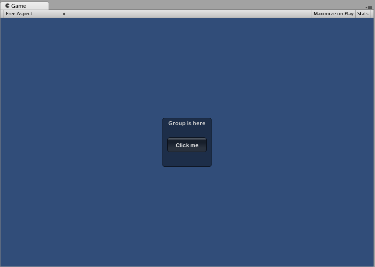
Вы также можете вкладывать несколько групп друг в друга. Когда вы так делаете, содержимое каждой группы обрезается по площади её родителя.
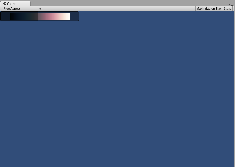
Области используются только в автоматическом режиме расположения. Они работают аналогично группам фиксированного расположения, т.к. определяют конечную часть экрана для содержания GUILayout контролов. Из-за природы автоматического расположения, вы почти всегда будете использовать области.
В режиме автоматического расположения, вы не определяется область экрана на уровне контролов, в которой будут отрисовываться контролы. Контрол будет автоматически расположен в самой верхней левой точке своей области. Ею может быть и экран. Вы также можете создавать области для размещения вручную. GUILayout контролы в какой-либо области будут расположены в левой верхней точке этой области.
Учтите, что ширина контролов с видимыми элементами (такими как кнопки и Box’ы), расположенных внутри области, будет растягиваться до полного заполнения длины области.
При использовании автоматического расположения, контролы будут по умолчанию появляться один за другим, сверху вниз. Существует ряд случаев, в которых вам может потребоваться более точный уровень контроля над тем, где расположены контролы и как они выстроены. Если вы используете автоматическое расположение, у вас есть выбор между горизонтальной и вертикальной группами.
Любые контролы внутри горизонтальной группы всегда будут размещаться горизонтально. Любые контролы в вертикальной группе всегда будут размещаться вертикально. Это звучит просто до тех пор, пока вы не начнёте вкладывать группы друг в друга. Это позволяет вам выстраивать любое количество контролов в любой конфигурации, которую только можно себе представить.
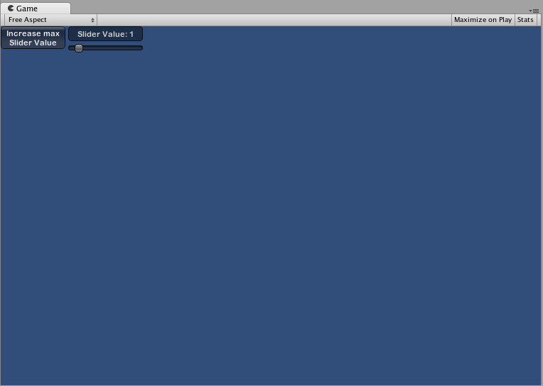
Использование GUILayoutOptions для определения некоторых контролов
Вы можете использовать GUILayoutOptions для переназначения некоторых параметров автоматического расположения. Для этого вам нужно передать опции в качестве последних аргументов GUILayout контролов.
Помните пример с областями, где кнопка растягивается на 100% ширины области? Мы можем это переназначить, если захотим.
Для полного списка возможных опций GUILayoutOptions, пожалуйста, простите страницу справки по классу GUILayoutOption.
