Что такое arduino debug
Debugging with the Arduino IDE 2.0
AUTHOR: Karl Söderby & Ubi De Feo
LAST REVISION: 12/15/2021, 08:33 AM
Overview
A newly introduced, yet less famous feature of Arduino IDE 2.0 is the Debugger.
A debugger is a software tool which is used to test and debug programs, hence the name.
It basically goes through a program in a controlled manner, with the help of a hardware interface which can help navigate through the program’s execution. This can be of aid in better understanding the program as well as helping spot potential flaws and code errors.
You can easily download the editor from the Arduino Software page.
Compatible Boards
The debugger is compatible with all SAMD boards. Boards using the SAMD architecture are the following:
Tutorials for the Atmel-ICE and J-Link debuggers uses the MKR WiFi 1010, but can be easily be applied to the boards listed above.
Requirements
You will also need one of the following hardware setups:
Additional accessories such as soldering iron, connectors, jumper wires and USB cables will also be required, depending on what hardware setup you use.
The Arduino Zero board can be used without any external hardware.
Hardware Setup
Below you will find three different tutorials that will help you set up and test the different hardware setups. We recommend you visit them, follow the instructions and come back here to learn how to use the tool!
Arduino Zero
The Arduino Zero does not require any additional hardware, as it already has a built-in debugger. This makes it a great choice for beginners that wants to learn more about debugging.
J-Link
Segger’s J-Link tool is a great option for advanced debugging. The J-Link tool can be connected to the MKR WiFi 1010 board by soldering, where a more detailed guide can be found in the link below:
Atmel-ICE
Atmel-ICE is another great option to use for debugging, and can also be connected to the MKR WiFi 1010 board through soldering. Learn more about debugging with the Atmel-ICE through the link below:
Getting to Know the Debugger
Once you have your hardware set up, we can continue to explore the Debugger tool in the Arduino IDE 2.0.
The Debugger is a brand new tool integrated in the Arduino IDE 2.0. You can easily access it from the sidebar on the left, grouped with the Board Manager, Library Manager, Search and Sketchbook Explorer.
Mind that doing so will only show you its inteface, but the real magic happens when you click the crossed out bug icon in the buttons menu at the top.
Now, in order to use the debugger, we need specific hardware instruments, the choice of which is very dependent on what kind of board/processor you are using, and you will almost always need an external debugger.
Using the Debugger
In order to use the Debugger, we need to upload a sketch to our board first, making sure that the built program will be optimized for debugging, so let’s check that option right away.
Important: You should connect the Arduino Zero through its programming USB port.
In this example, we are going to choose the basic blink sketch. You can easily access this code through File > Examples > Basics > Blink. Upload the code to your Arduino board. When it is finished, it will let you know in the output panel at the bottom.
Once your program has been uploaded, we can start using the debugger.
Breakpoints
Let’s begin by creating something called a breakpoint. Breakpoints are used to stop the program execution at a specific line (or when a specific condition is verified). We can use multiple of these in a program (the number is variable depending on the processor).
In this example, we are going to set a breakpoint for line 33 and line 36. These are set by clicking to the left of the line numbering in the editor.
We can now go through our code, step by step. The first (automatic) stop will be triggered by the Debugger itself, and it will be a standard entry-point, ignore that for now.
Let’s continue, by clicking on the Play/pause button (Continue). The program will now run to the first breakpoint, line 33. If we click it again, it will jump to line 36 (the lines 34 and 35 will still be executed but we won’t see that). Clicking the Play/pause button again will continue running the program which will pause at its next breakpoint, line 33. We’re in the main loop, after all.
Step over
The step over feature basically goes through the operations of a program, step by step. Let’s say we have 20 operations in our program, each doing something unique. The step over can in a way step through these, one by one, and analyse what’s going on at each step.
Step in and Out
Next up is the step in and step out commands. In this example, we are using the and functions. Using step in we basically branch out of the code we wrote, and jump into the code where these functions are defined. In this case, we are inspecting code inside a file which is part of the Arduino framework.
The step out feature is basically the opposite: it returns you to the origin point, and moves to the next step.
Conclusion
In this guide, we have covered some basics on using the Arduino IDE 2.0 Debugger. We explored some different hardware setups that we can use, how to navigate the Debugger tool, and linked some more elaborate hardware guides to make your debugging experience more smooth!
We hope you enjoy the Debugger, and if you are having issues, please report them in Arduino IDE GitHub repository.
More Tutorials
You can find more tutorials in the Arduino IDE 2 documentation page.
4 Simple Steps for Debugging Your Arduino Project
How to Debug Your Arduino Project
Anyone who’s written code in the past can tell you that it usually doesn’t work as initially expected. In fact, when it comes to writing code, debugging is an essential part of the creative process. However, Arduino debugging can be a little more complicated. One of the reasons for that is that Arduino doesn’t come with a custom debugging tool.
Most programs will use a debugger to help the programmer locate bugs and address them. Yet Arduino has no such debugging system. Arduino Debugging is one of the more challenging tasks of managing an Arduino project. Unlike most other IDEs, there is no official Arduino debugging feature onboard the Arduino IDE. Many users are surprised at the absence of a dedicated Arduino debugging tool.
On Arduino, once you run your program you are unable to see what’s happening inside your device and how your code is running. The only assistance you’re given comes in the form of messages on your serial monitor or by LED display. Especially when other IDEs usually have debugging tools that utilize breakpoints, steps, call stack, watch, local/global variables and other components to double check through code.
However, debugging Arduino code isn’t the same as debugging code on a PC. The two are very different in terms of how they are approached. The main reason for this is that Arduino code is usually used to control physical outputs or receiving physicals inputs to/from the real world and the debugging process has to take those into account.
In practice, this means that Arduino developers often have to explore alternative methods and tools to debug their code. In this post, we’ll break down everything from Arduino code debugging to using a simulator to debug Arduino. This will give you all the information you need to produce code that works.
Design
When it comes to creating an Arduino Project your project’s overall design is very important. From the moment you start choosing components for your project, you need to have a clear idea of your end product in mind.
For example, if you want to design a sketch that runs on an Arduino board and lights up LEDs, you need to provide the foundations within the design phase of your project. The overall design of your sketches and your circuits will determine how your finished project looks.
Build
In terms of building your project, this is where you actually give life to your circuit. The ‘build process’ is where the Arduino IDE compiles your C++ sketch into machine code which is then uploaded straight to your Arduino board.
Circuito.io Code
The code you get from circuito.io is actually a test code without any logic. This test code is used to check that all your components are wired properly and function correctly. This helps to check that there are no faults with your hardware setup. circuito.io also provides you with code libraries for all the different components you chose. If your test code fails, then you know you need to start the debugging process.
Step 1: Check your hardware
As mentioned above, if your circuito.io code doesn’t work, chances are you have a problem with your hardware. This means you need to begin Hardware debugging.
Here are some basic troubleshooting steps for hardware issues:
Step 2: Code debugging
If your test code works, it’s time to write your own code. When writing your own Arduino code, there are a number of basic rules and best practices you should follow. By following the instructions below, you’ll have a much easier time if you need to debug it later on:
Compilation
If you get a compilation error when trying to compile or upload code to your board check for errors in syntax, typos and more. Using the correct syntax is vital for making sure your code compiles. When compilation fails, the IDE will present you with the errors on its bottom part. However, the error messages generated by the Arduino IDE are limited in their description and therefore not always very helpful.
If you understand what the error message means, try fixing the problem it indicates and compiles again. This is a convenient form of Arduino troubleshooting.
However, if you address an error listed on the IDE and the sketch still doesn’t compile, it’s a good idea to use Google to search for solutions to the problem.
Common syntax errors are:
Arduino has a large open source community with extensive Arduino troubleshooting guides, which will help you to identify problems with your code. Once you’ve solved the problem and your code works, click run.
Run code
If your code compiles and uploaded successfully to the board but doesn’t run as expected you need to begin debugging.
Serial Monitor
As outlined above, if your code fails when you try to run your sketch, you need to start debugging your code. First, think and define which parameters to print and use the serial monitor to monitor them on screen(You can learn the basics of serial print here). The aim is to print an overview of the current state of the program. As such:
Check Your Code Manually
One good way to assess the quality of your code and check for errors is by going through your code manually. You can do this by:
Step 3: Using external software Debugging tools
If you check your code manually and still can’t find the problem, it’s time to use an advanced debugging tool. Whereas many IDE’s have their own onboard debugging tool, Arduino doesn’t. However, there are a number of external tools you can use to make sure your code is running correctly. Here are some of the best tools to consider if you need advanced debugging and simulation options:
Visual Micro
Visual micro is a plugin available via Microsoft Visual Studio that is used to create cross-platform programs on Arduino. Any code created in Visual Micro that adheres to Arduino will be accepted. Visual Micro is great for collaborative teams debugging Arduino because it enables shared code and library editing. Code can be created across different platforms and combined with the program code throughout the build process. Visual Micro also offers GDB debugging and Serial, Bluetooth and Wifi debugging.
Atmel studio
DebugWIRE
DebugWire is a protocol of Atmel to debug many ATTiny (e.g. ATTiny 13, 85) and ATmegas (e.g. ATmega48/88/168/328) without JTAG, only via the Reset pin. The DebugWire protocol is not documented by Atmel but some guys reverse engineered big parts of the protocol, and were able to build some simple debuggers. By using debugWIRE one has full read and write access to all memory and full control over the execution flow. It supports single-step, run-to-cursor, step-out, and software break instructions.
Step 4: Using Arduino simulators and emulators
More tools you can use for monitoring and debugging are Arduino emulators and simulators. Arduino simulators have made it easier than ever before for experts and hobbyists alike to program and test their ideas until they run efficiently. Hardware simulation is a complex process and while in the industry there are amazing tools for hardware debugging these tools are quite limited for makers and hobbyists.
However, simulators and emulators still have a place among the Arduino user’s debugging toolkit. Arduino simulators support line-to-line debugging which allows the user to look through their code and establish where they went wrong. Here are just a few advantages of using simulators:
Debugging
As mentioned above, simulators are great for debugging Arduino, both in terms of syntax and functional errors. What makes simulators suitable for debugging is that you can write code and create electronic circuits to test the integrity of your code. Some simulators will offer you a limited library of hardware to test whereas others will allow you to develop complex virtual environments. Today, you can even use simulators to render your project in 3D.
You can see what the program does
One of the biggest advantages provided by simulators is transparency. When running a simulation you can see exactly how your code works and identify ways it can be improved. This allows you to run new code without worrying about damaging your board or equipment.
Compared to IDE and hardware setups, simulators allow users to correct functional programming errors. Without a simulator, you can only address non-functional, technical mistakes in your code such as syntax errors. This makes simulators ideal for newer users who will need to undergo a lot of trial and error before they reach the finished product. Testing code via a simulator ensures that hardware stays operational, saving time and money.
Plotting and logging
Simulators not only allow you to test how your code runs, but allow you to log and plot the data generated as well. You can take note of your programming data and plot it on an external program like Excel. Logging data on your program and your additional devices helps to develop insights that can help refine your coding.
Experimentation
In terms of experimentation, simulators and emulators are hard to beat as well. Without a simulator, the user is confined to creating code based on their theoretical knowledge and has limited opportunities to try out new code and new components (especially when mistakes result in damaged hardware). With a simulator, you can test the code in a virtual environment and try out new ideas without worrying about the end result.
Testing new components
Likewise, simulators offer you a way to test out components before you pull the trigger and make a purchase. This way you can see if a part will be of use to your project, and practice integrating it into your overall environment. This ensures that you don’t waste money on buying parts that are of little to no use.
Create blueprints for electronic circuits
When constructing an electronic circuit, you can use a simulator to design, build and preview schematics. This cuts out much of the legwork of needing to manually draw up blueprints for electronic circuits saving you time. In addition, it also ensures that the end circuit design is adequately optimized.
Popular Simulator
1. Electronics Lab on Tinkercad (formerly circuits.io)
The Circuits.io platform makes it easy for users to simulate real-world electronics through a circuit simulator. This online simulator allows the user to drag in an Arduino board and start programming. It also offers the user a circuit diagram maker, multimeter measurement tool and oscilloscope. This Arduino simulator allows you to build your design from scratch whilst enabling you to take precise measurements of the power supply throughout your circuit.
2. Virtual Breadboard
Virtual Breadboard has established a name for itself as one of the most powerful and advanced Arduino simulators available today. Virtual Breadboard has grown within the electronic circuit industry and today can simulate Arduino devices, Netduino and PIC microcontrollers. On start up the user has access to a complete virtual development environment where they can program directly to an Arduino board. It’s also worth noting that it can act as an AVR emulator as well.
Debugging Arduino Doesn’t Need to be Difficult
When you start using Arduino, debugging can seem like a complicated process, but if you break it down into steps, you will probably be able to overcome the problems and learn a lot along the way.
As you saw in this guide, there are a variety of external tools to help you but the best way to debug is by trial and error, identifying faults along the way and fixing them as you go.
Another method that will help you cut down on the number of errors you encounter is to be strict with your syntax. This will ensure that when the time comes to debug your code you won’t have to sift through syntax errors which could have been eliminated during your write up.
Compared to an IDE with an onboard debugger, debugging an Arduino can be quite inconvenient. If you test, compile and run your code before putting it through a third party debugger, you’ll be well on track to producing quality code. Likewise, if you get lost along the way there’s a vibrant open-source community on hand to help.
Отладка Arduino через debugWire (Atmel Studio и AVR Dragon)
В этой статье поговорим о том, как отлаживать программы на плате Arduino UNO с помощью debugWire. Я частенько использую эту платку или Nano для отладки своих программ в Atmel Studio (использовать Arduino IDE у меня рука не поднимается). И так начнем.
Что можно сделать с помощью debugWire?
Прочитать память контроллера, выполнить пошаговую отладку кода, установить точки останова программы, прочитать регистры и значения на портах ввода/вывода и т.п.
Что для этого будет необходимо?
— Arduino Uno
— Atmel Studio 6
— AVR Dragon программатор-отладчик
Подготавливаем железо
В даташите на Atmega328 говорится:
«Конденсаторы, подключенные к пину RESET, должны отключены при использовании debugWire. Все внешние источники сброса должны быть отключены»
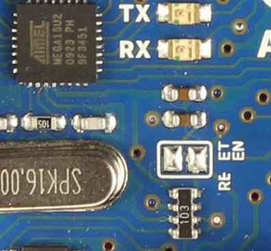
Если проверить схему Arduino Uno, можно увидеть, что к RESET подключен конденсатор 100нФ. В старых версиях Arduino необходимо было снять этот конденсатор для отключения RESET. На новых платах есть специальная перемычка, которая может быть разрезана и запаяна вновь, если потребуется.
Подготовка софта
Просто компилируем код в Atmel Studio, нет необходимости заливать программу отдельно через AVR DUDE, AVR Dragon сам сделает это через debugWire.
Подключаем железо
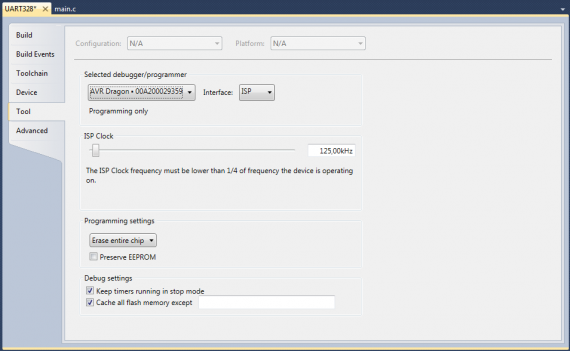
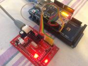
Подключаем ISP от AVR Dragon к ISP Arduino Uno. Обратите внимание, что контакт 1 подключается к PIN1 на другом устройстве, т.е. MISO подключается к MISO. AVR Dragon и Arduino запитываются каждый через свой USB разъем. В настройках выбираем использовать AVR Dragon в качестве отладчика.
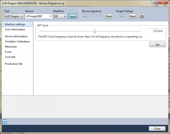
Открываем меню программирования Tools > Device Programming
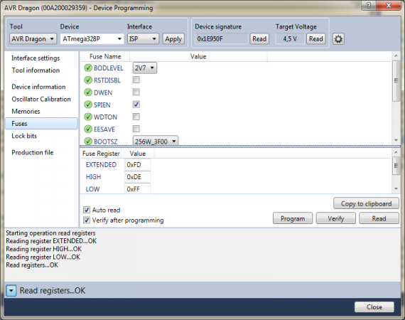
Внимание «шьем» фьюзы
Собственно устанавливаем фьюз-бит DWEN. В даташите также сказано что LOCK биты не должны быть запрограммированы.
Запускаем debugWire
1. После того как прошили фьюзы временно отключаем питание Arduino Uno.
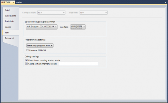
2. Устанавливаем debugWire как интерфейс для программирования и отладки
3. Жмем «Start Debugging and Break» или Alt+F5. Можно просто нажать F5, а уже потом точки останова расставить. Отладка запускает прошивку тоже.
4. Отлаживаем программу, устанавливаем где надо точки останова, наблюдаем за регистрами и портами ввода-вывода.
5. Останавливаем отладку Ctrl+Shift+F5, изменяем код и возвращаемся к пункту 3.
6. Жмем меню «Debug > Disable debugWIRE» Это меню доступно только во время отладки, так что, если что жмем снова F5. После это DWEN сбрасывается и можно снова использовать ISP.
Вот и все.
Отладка кода Arduino (AVR). Часть 1. Виртуальная отладка
Предисловие
Сборка при помощи Makefile
Прежде чем мы подойдём к описанию отладки в железе (во второй части) нам нужно немного потренироваться. Вероятно многие знают, что среда Arduino вызывает компилятор avr-gcc со всем окружением, автоматически настраивает параметры его вызова и запускает процесс сборки. Так вот, нам нужно повторить этот процесс явно. Делать это мы будем не вручную, хотя некоторые телодвижения всё-таки понадобятся. Нужно это для того, чтобы получить отладочный объектный файл в формате ELF. Среда Arduino подчищает за собой и у нас нет доступа ни к опциям компилятора, ни к результатам компиляции.
Это подводит нас к вопросу использования утилит для автоматической сборки avr-gcc проекта, а ещё точнее — скетча с библиотеками Arduino. Тут можно было бы погрустить, т.к. дело это не простое, но, как говорится, всё уже сделано до нас. Оказывается, на github уже есть всё необходимое именно для сборки скетчей с библиотеками Arduino. Проект называется Arduino-Makefile. Как не трудно догадаться из описания, этот проект содержит Makefile для автоматической сборки проектов на Arduino. Из перечисленных в описании особенностей мы обратим внимание только на некоторые.
Пакет Arduino-Makefile — это набор конфигурационных файлов, примеров и описаний. В нём нет утилит, которые всё это должны использовать. Нет также и среды разработки, т.е. сборка осуществляется через командную строку. Это означает, что вы можете прикрутить любую удобную для вас IDE, которая поддерживает сборку через Makefile. Я обычно использую Visual Studio.
Если внимательно посмотреть на содержимое, то можно заметить, что есть один глобальный универсальный Makefile (Arduino.mk), который включается в специфические местные файлы сборок. Вам нужно указать только частные (минимальные) настройки для конкретной цели сборки, а остальное будет выполнено в автоматическом режиме (настройка переменных, поиск зависимостей и прочее). Это очень удобно, как будет показано ниже.
Инструментарий
Мы выяснили, что можем собирать скетчи. Теперь посмотрим как будет организован сам процесс сборки и отладки. Я обещал показать два способа. У каждого из них есть свои плюсы и минусы. Сделаем их краткий обзор.
Способ 1. Создаём отладочный файл, загружаем его в Proteus, отлаживаем там же.
Достоинства:
— относительная простота отладки (с подключением монитора последовательного порта нужно будет только помучиться);
— доступ во внешний мир через последовательный порт;
— построение графиков (доступны виртуальные измерительные приборы);
— возможность моделировать схему в режиме реального времени;
— в отдельных окнах доступны регистры мк, области памяти, глобальные переменные и исходный код, конечно, в том числе его ассемблерный вариант.
Недостатки:
— платность Proteus;
— ограниченный набор периферии;
— сложные модели не могу учитывать всех особенностей оригинальных компонентов.
Способ 2. Создаём отладочный файл, загружаем его в AVR Studio 4, отлаживаем, используя специальный плагин Proteus VSM Viewer для AVR Studio 4.
По достоинствам и недостаткам почти то же, что и способе 1. Можно добавить, что AVR Studio показывает подробное дерево всех регистров моделируемого мк, вплоть до битов, что очень удобно. Из минусов стоит отметить, что отладка оптимизированного кода имеет свои особенности и не так просто понять как заставить отладчик останавливаться в нужных местах.
Способ 3. Создаём отладочный файл, загружаем его в AVR Studio 4, отлаживаем, используя программный эмулятор JTAG ICE mkII и специальный адаптер (HappyJTAG2).

Достоинства:
— это настоящая отладка в реальном «железе» с использованием JTAG ICE mkII отладчика (поддержка мк вплоть до ATmega2560);
— HappyJTAG 2.45 работает на Windows 7 x64, нужно только пропустить одно окошко, где просят всё-таки купить драйвера.
Недостатки:
— замечена нестабильная работа HappyJTAG2 с небольшими по объёму исходниками;
— нестабильная работа AVR Studio при выполнении отладочных действий;
— автор HappyJTAG2 давно забросил своё детище (видимо с приходом AVR Studio 5 и Atmel Studio);
— некоторые особенности подключения (COM4 или один из первых 4-х последовательных портов должен быть свободен или отсутствовать, т.к. AVR Studio перебирает COM1-COM4 в поиске отладчика). Именно свободен или отсутствовать, т.к. HappyJTAG2 работает, так скажем, «изнутри».
Как вы видите я показал три способа, но в настоящее время практически у меня заработали только два из них. Первый способ будет описан в этой статье. Второй способ, к сожалению, мне не удалось повторить. Нужно найти «совместимую» комбинацию Proteus и AVR Studio. На картинке использована последняя студия AVR Studio 4.19.730 и Proteus 7.7 SP2. Когда-то давно я использовал этот способ, но при наличии железного отладчика пользоваться им не имеет особого смысла. Третий способ я оставил для второй части. Там нужен будет адаптер и описание его подключения к платам Arduino, поддерживающим отладку по JTAG.
И что же для этой всей кухни нам понадобится? Для начала нужно забыть про убогое Arduino IDE, его можно использовать только для контрольных проверок при сборке скетчей. Далее, нам понадобятся:
Будем считать, что вы знаете как спросить у Google где достать всё это хозяйство. На всякий случай я приведу полезные ссылки в конце статьи. Некоторые комментарии по поводу инструментария.
Как известно, Proteus платный, но это не самое печальное. К сожалению, его библиотеки не на столько близки к реальному миру, как хотелось бы. К примеру, Ethernet shield W5100 вы промоделировать в нём не сможете (по крайней мере в версии 7.x). Поэтому, уважаемые последователи Arduino, идите истинным путём. Только отладка и только в железе спасут ваши души от неправильно поставленных вопросов. Proteus мы будем использовать как инструмент обучения, а в полевых условиях — только JTAG.
Отладка скетчей Arduino (AVR) в Proteus 7.x
Хватит общих слов, теперь конкретики. Есть много вариантов запуска процесса сборки, их все не распишешь, поэтому я остановлюсь на конкретно одном и постараюсь описать его понятно. Увидев общую схему, вы сможете применить её на свой набор средств разработки. Для удобства я разобью описание всего процесса по шагам, некоторые можно будет пропускать. Надеюсь, что даже самые неопытные пользователи Arduino поймут о чём речь.
Шаг 1. Скачиваем и устанавливаем среду разработки Arduino. Для определённости допустим, что она будет из серии 1.6.x. Здесь сразу сделаю несколько замечаний. Вообще, от Arduino нам нужны только библиотеки. Если не считать всего остального, то сама идея упрощённого вида программы очень даже хороша (если сравнить C# и C++ или, не дай боже, C++/CLI, то это небо и земля). Отсутствие же нормальных отладочных средств привело, прямо скажем, к безграмотному программированию. Вместо того, чтобы осознанно превращать задуманный алгоритм в программный код, пользователи Arduino вынуждены делать комбинации из магических заклинаний, выцеживать инфу через Serial.print() и только некоторые пытаются статически прочитать исходники библиотек. Тяжко на это всё смотреть.
Я отвлёкся, а вы, наверное, успели поставить среду по стандартным путям. Желательно, чтобы папка Arduino находилась в корне раздела (C:\Arduino). Это связано с путями в makefile, которые не любят пробелы в «Program Files». Мы позже будем настраивать пути и для тех, у кого папка уже в «Program Files» придётся сделать одну сложную для пользователей Windows вещь — junction point на папку. Возможно, пробел можно экранировать, но я этого не пробовал.
Для определённости, допустим, что путь к среде такой: C:\Program Files\Arduino.
Шаг 2. Скачиваем и распаковываем Arduino-Makefile. Содержимое папки Arduino-Makefile-master распаковать в C:\Arduino-Makefile. Хочу сразу отметить, что внутри есть файл README.md, который лучше посмотреть на github’е, где много чего описано. Также следует взять на заметку файл arduino-mk-vars.md, который содержит описание используемых в пользовательском (проектном) Makefile переменных.
Для работы утилиты make нужен комплект gnu bin utils, который входил в состав WinAVR в своё время. Я не знаю есть ли официальный сайт сборки этих самых утилит под Windows, но можно поступить следующим образом. Вам нужно будет скачать старый добрый WinAVR последней версии и вытащить из него папку utils, где находятся командные утилиты. Можно установить, скопировать папку и деинсталлировать WinAVR (потому что в его комплект входит старый компилятор avr-gcc, который нам не нужен).
Далее, к примеру, создать папку c:\avr-gcc и скопировать utils в неё. После этого добавить в переменную PATH (через свойства Компьютера) путь C:\avr-gcc\utils\bin:
set PATH=C:\avr-gcc\utils\bin;%PATH%
Путь должен быть одним из первых в поиске. Не забывайте про это изменение, т.к. оно может повлиять на работу других программ, если вы используете другие подобные среды разработки.
Шаг 3. Сами знаете где берёте/покупаете Proteus [7.2 — 7.8]. Почему именно этой серии и такой интервал версий? Потому что я их пробовал и вроде бы на несложных проектах они вполне неплохи. Версии больше 7.8 не могли подгрузить объектный файл одного моего проекта в IAR, а ниже я не пробовал. Восьмёрка просто глючная пока, может быть потом кто-то напишет что-то и про неё. Здесь мы с вами возьмём конкретно Proteus 7.8 SP2.
Шаг 4. Используя статью, создаём junction point на папку с установленной средой Arduino, т.е. C:\Arduino должна ссылаться на C:\Program Files\Arduino. Это нужно, чтобы не мудрить с поддержкой пробелов в makefile’ах. Т.о., не копируя папку с Arduino, мы получили её копию в нужном нам месте. Кто пользуется Far’ом может использовать комбинацию Alt+F6 на папке.
Пишем пример программы для тестирования сборки из среды Arduino, назовём её Example1 и сохраним в папке скетчей:
void setup()
<
DDRD |= ( 1
Компилируем и проверяем, что сборка проходит. У меня в Arduino 1.6.7 компоновщик объектных файлов (ld.exe) вылетел с ошибкой, я заменил его на другой (можно, к примеру, из этой сборки).
Шаг 5. Копируем файл C:\Arduino-Makefile\examples\WebServer\Makefile в папку с нашим скетчем: C:\Arduino-Makefile\examples\Example1. Исправляем его содержимое следующим образом:
# Arduino Make file. Refer to https://github.com/sudar/Arduino-Makefile
# Suppress printing of Arduino-Makefile configuration.
#ARDUINO_QUIET = 1
# Device type as listed in `boards.txt` or `make show_boards`.
BOARD_TAG = mega
# Microcontroller model.
# Usually can be auto-detected as `build.mcu` from `boards.txt`
MCU = atmega2560
#CPU speed in Hz
#Usually can be auto-detected as `build.f_cpu` from `boards.txt`, except in
#some 1.5+ cores like attiny where there is a clock submenu.
#F_CPU = 16000000L
# What name you would like for generated target files.
# Defaults to the name of your current working directory, but with underscores (_) instead of spaces.
#TARGET = project
# Baudrate of the serial monitor.
# Defaults to `9600` if it can’t find it in the sketch `Serial.begin()`
MONITOR_BAUDRATE = 9600
Вставляем вначале нашего исходника строчку, подключающую явно Arduino.h (это делать необязательно, если есть зависимости от библиотек, указываемые в переменной ARDUINO_LIBS):
void setup()
<
DDRD |= ( 1
Не забываем сохранить исходник и Makefile. Далее, находясь в папке Example1, вводим команду make (при помощи консоли или в Far’е, или другим удобным способом), должна появиться большая портянка, похожая на ту, что выводится в Arduino IDE при включении вывода полной информации о процессе сборки. Это если всё было сделано правильно, если же что-то не получилось, то попытайтесь сначала самостоятельно понять что не так, а потом уж пишите комменты к статье.
Поскольку мы в Makefile закомментировали строку ARDUINO_QUIET = 1, то перед информацией о сборке идёт шапка со значениями переменных самого Makefile. Часть из них задана, а другие вычисляются по ходу выполнения. Это помогает находить ошибки при правке Makefile проекта.
Будем считать, что всё прошло успешно, тогда у вас должна появиться папочка build-mega, в котором наш долгожданный Example1.elf — этот тот самый файл, ради которого всё действо затевалось. Этим файлом мы «прошьём мозги» виртуальному мк в Proteus и заживём… с ещё одной степенью свободы.
Шаг 6. Вернёмся к Proteus. Создаём новый проект (dsn-файл) в папке с исходником. Достанем из недр библиотек компонент — микроконтроллер ATmega2560 и вставим его куда он поместится, уж здоровый больно. Заполните свойства компонента по картинке. Устанавливать COMPIM пока не обязательно, он понадобиться для работы с монитором.
Затем входим в режим отладки Debug\Start/Restart Debugging. Получите картинку, похожую на такую.
Ну, а дальше, всё зависит от полёта вашей фантазии. В окошке исходников будет доступен не только Example1.ino, но и другие зависимые исходники. Можно раскрыть ассемблерный код, регистры процессора, память и что-то там вроде ещё. Читайте доку на Proteus.
Шаг 7. Нужно настроить монитор. Писать лень, надеюсь сделаете это уже самостоятельно. Смысл, вкратце, такой. Создаёте два виртуальных последовательных порта, соединённых нуль-модемом (лучше с номерами больше COM4). Один прописываете в компоненте COMPIM Proteus, а второй в терминальной программе (PuTTY). Не забудьте поправить скорость и кодировку вывода в терминальной программе, по идее она должна совпадать с кодировкой исходных файлов, если захотите делать вывод в монитор по-русски.
Шаг 8. Если хотите использовать avr gcc 4.9.2, то нужно положить содержимое архива в корень диска и исправить путь в переменной AVR_TOOLS_DIR. Только там у меня не заработал avr-size, кажется. Можно поменять его на тот, что идёт в комплекте WinAVR (или Arduino).
Кстати, чтобы размер выводился в нормальном виде нужно добавить опцию в вызов avr-size (файл Arduino.mk):


