Что такое pvid mikrotik
MikroTik Bridge vlan и Q-in-Q без костылей
Пытаемся понять как настроить vlan и q-in-q на простом примере, без углубления в теорию, простенько и со вкусом
На днях задали интересный вопрос по поводу q-in-q, и родилась идея описать простыми словами, как настраивать q-in-q на bridge без каких-либо костылей в виде саб интерфейсов vlan.
Прежде чем начать, обговорим топологию сети.
Есть пять коммутаторов, они как-то соединены, и рождается некая топология сети.
Пояснительная записка к нашей сети.
Коммутаторы, которые имеют имя SW-# это коммутаторы «уровня доступа» к ним подключается конечное оборудование.
Номер метки STAG 100 q-in-q.
Всё сервера подключены в access порты, т.е. фреймы сервера отправляют без тега.
Синий vlan 400 управления, он должен быть на каждом коммутаторе как логический интерфейс, а также тэгом отправляться на SRV-4 предполагаем, что на данном сервере запущенна система мониторинга, которая собирает какие-то метрики с коммутаторов или там живёт наш админ =).
И так начнём с самого простого на всех коммутаторах создадим bridge и добавим в него порты, указанные на схеме, естественно я не буду показывать, как это делать на каждом коммутаторе так как процедура однотипная, все делаем по дефолту.
И так далее на каждом коммутаторе, меняем только количество и имена интерфейсов.
На всех коммутаторах подготовим интерфейс управления отдельный и единственный sub interface vlan
Да, да, я именую интерфейсы vlan через точку, где перед номером тега указываю имя интерфейса родителя.
Ну а теперь начнём, настраивать коммутаторы с пояснением.
Нам необходимо, указать, следующее:
Делается это одной командой просто устанавливаем pvid на данный интерфейс.
Далее нам необходимо, 200 vlan отправить с тегом в ether2, опять же делается одной командой.
Также на этом коммутаторе у нас есть 400 vlan управления, так как получить доступ надо к IP (читай CPU) указываем помимо ether2 также порт сам bridge. А также так как мы должны в первой порт отправлять данный трафик с тегом, указываем ещё и ether1
Создаём access порты доступа или просто untagged
Заполняем таблицу VLAN тегированным портами.
По аналогии с SW-1 и SW-2 Создаём access порты доступа или просто untagged
Заполняем таблицу VLAN тегированным портами.
Переходим непосредственно к Q-in-Q
На всех коммутаторах QSW сменим тип ethernet
А теперь по всем коммутаторам
Заполним таблицу vlan
обратите внимание, что мы добавили, 100 vlan.
Но появляется проблема, в том, что SW-2 нам шлёт трафик с типом ethernet 8100, а наш коммутатор (bridge) работает 88a8, мы должны каким-то образом указать коммутатору, что в данном порту что-то другое.
Нам необходимо указать, что весь трафик с ether2 оборачивать меткой 100, мы уже знаем, что это делается с помощью pvid, но для того, что коммутатор понимал, что он должен ожидать не 88a8, а 8100 мы должны указать tag-stacking=yes
Вообще без комментариев, так как всё понятно
Так же без комментариев.
Management на QSW
И осталось небольшой момент, который надо исправить у нас management трафик в 400 vlan бегает только между SW коммутаторами, но не доступны QSW, дело в том, что тот интерфейс который мы создавали пытается «поймать» 400ую метку на интерфейсе CPU, но она обёрнута 100 меткой и чтобы наш 400ый мог достучаться, нам надо отправить трафик без метки в CPU т.е в сам bridge, делается это с помощью всё того же пресловутого pvid на самом интерфейсе бриджа и естественно мы должны указать как pvid 100, метка которая оборачивает наш 400ый vlan.
На всех коммутаторах QSW выполняем
Соответственно если у вас в разрыве будет стоять коммутаторы, которые будет через себя «таскать» только q-in-q ваша задача перевести коммутатор в 88a8 и работать как с обычным vlan, но только с верхней меткой, в нашем случае 100, а на внутренние метки не обращать внимания.
Я знаю, я много не договорил и многое не описал, многие термины я специально упустил и постарался объяснить простыми словами.
Стоит заметить, что существует не один способ организации VLAN трафика на Mikrotik. Но только один из этих способов конфигурации VLAN является наиболее корректным, позволяющим исключить проблемы с производительностью и подключением.
Начиная с версии RouterOS 6.41 стало возможно использовать мост для фильтрации VLAN и именно эта конфигурация рекомендована официальным Wiki Mikrotik.
Освоить MikroTik Вы можете с помощью онлайн-куса « Настройка оборудования MikroTik ». Курс основан на официальной программе MTCNA. Автор курса – официальный тренер MikroTik. Подходит и тем, кто уже давно работает с микротиками, и тем, кто еще их не держал в руках. В курс входит 162 видеоурока, 45 лабораторных работ, вопросы для самопроверки и конспект.
Рассмотрим базовую конфигурацию VLAN позволяющую разделить локальную сеть на два виртуальных сегмента для разных отделов офиса.
Базовая схема коммутации VLAN
Для начала нам необходимо создать мост bidge1 с фильтрацией VLAN. Для включение фильтрации VLAN перейдите во вкладку VLAN и отметьте пункт «VLAN Filtering».
Мост с фильтрацией VLAN
В статье я буду приводить примеры настроек как для графического интерфейса так и для консоли.
Добавляем порты в мост bidge1 и назначаем им PVID.
Добавление access порта с PVID в bridge
Добавляем соответствующие записи в VLAN таблицу моста.
VLAN таблица моста
В случае работающей VLAN фильтрации на bridge таблица VLAN выглядит примерно так:
Освоить MikroTik Вы можете с помощью онлайн-куса « Настройка оборудования MikroTik ». Курс основан на официальной программе MTCNA. Автор курса – официальный тренер MikroTik. Подходит и тем, кто уже давно работает с микротиками, и тем, кто еще их не держал в руках. В курс входит 162 видеоурока, 45 лабораторных работ, вопросы для самопроверки и конспект.
Всё гениально и просто.
Спасибо кеп!
Подскажите пожалуйста, в некоторых мануалах видел, что на этапе добавления записей в таблицу VLAN добавляют помимо портов еще и бридж, в каких случаях это нужно делать, а в каких нет?
Если вы повесите vlan на бридж, то он будет доступен на всех интерфейсах (портах) входящих в этот бридж, вот и все.
вопрос был не про vlan в бридж, а бридж во vlan, например в поле tagged, а делаю это для того, чтобы vlan имел доступ к процессору роутера, так как бридж по сути является портом cpu, и если не добавить бридж в вилан, то из этого вила не будет доступно, например, управление роутером.
Не понимаю о чем вы, что за доступ к процессору и порты cpu? Бридж не может быть никаким портом cpu! Если вы работаете с vlan, то вам нужно для начала понять что это такое, разобраться в понятиях trunk и access порта. И тогда больше не будете терять доступ к управлению микротиком.
Если вы хотите в порт микротика отправлять vlan и при этом чтобы подключенный на этот порт клиент работал без vlan (не умеет работать с vlan), то вам нужен access порт.
Не надо создавать фильтрацию vlan на существующем бридже, через который осуществляется управление микротиком. Здесь ключевое слово СОЗДАТЬ мост.
У вас по записям и по картинкам как раз и управление и фильтрация на одном бридже bidge1
Manual:Bridge VLAN Table
Applies to RouterOS: 6.41+
Contents
Summary
Since RouterOS v6.41 it is possible to use a bridge to filter out VLANs in your network. To achieve this, you should use the Bridge VLAN Filtering feature. This feature should be used instead of many known bad VLAN configurations that are most likely causing you either performance issues or connectivity issues, you can read about one of the most popular misconfiguration in the VLAN in a bridge with a physical interface section. The most important part of the bridge VLAN filtering feature is the bridge VLAN table, which specifies which VLANs are allowed on each port, but configuring it might get quite complex if you are trying to make more advanced setup, for generic setups you should be able to configure your device using the Trunk and Access ports example, but the purpose of this guide is to provide in-depth explanation and point out some of behavior characteristics when using bridge VLAN Filtering.
Background
Before explaining bridge VLAN filtering in-depth, you should understand a few basic concepts that are involved in bridge VLAN filtering.
Trunk/Access port setup
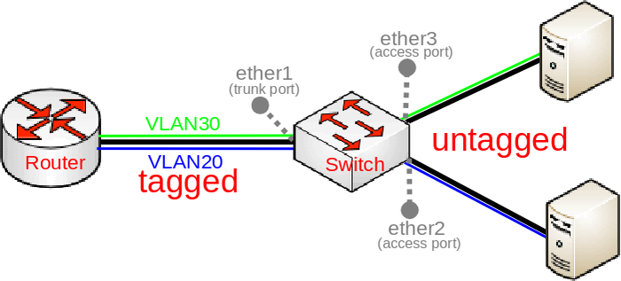
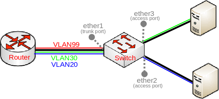
Below you can find a very common diagram for a very typical type of setup that consists of a trunk port and multiple access ports:
This setup is very common since it gives the possibility to divide your network into multiple segments while using a single switch and maybe a single router, such a requirement is very common for companies that want to separate multiple departments. With VLANs you can use different DHCP Servers, which can give out an IP address from a different subnet based on the VLAN ID, which makes creating Firewall rules and QoS a lot easier.
In such a setup you would connect some very generic devices like Desktop PCs to ether2 and ether3, these can be considered as workstations and they generally only use untagged traffic (it is possible to force a VLAN tag for all traffic that is sent out a generic workstation, though it is not very common). To isolate some workstations from other workstations you must add a VLAN tag to all packets that enters ether2 or ether3, but to decide what VLAN ID should the packet get is to use a concept called Port based VLANs. In this concept packets get a VLAN tag with a VLAN ID based on the bridge port to which the device is connected. For example, in this setup the device on ether2 will get a VLAN tag with VLAN20 and the device on ether3 will get a VLAN tag with VLAN30, this concept is very scalable as long as you have enough bridge ports. This should give you the understanding that traffic between the bridge and devices behind ether2/ether3 is untagged (since there is no VLAN tag, hence the name).
When we have determined our untagged ports, we can now determine our tagged ports. Tagged ports are going to be the trunk ports (the port, that carries multiple VLANs) and usually this port is connected to a router or another switch/bridge, you can have multiple trunk ports as well. Tagged ports are always carrying packets with a VLAN tag (hence the name) and you must ALWAYS specify the tagged ports for each VLAN ID you want this port to forward. It is possible that a port is a tagged port for one VLAN ID and the same port is an untagged port for a different VLAN ID, but this is for a different type of setup (Hybrid port setup).
To configure the trunk/access port setup, you need to first create a bridge:
Warning: Don’t enable VLAN filtering yet as you might get locked out from the device because of the lack of the management access, which is configured at the end.
Add the bridge ports and specify PVID for each access port:
Note: PVID has no effect until VLAN filtering is enabled.
Add appropriate entries in the bridge VLAN table:
You might think that you could simplify this entry with a single entry, similar to this:
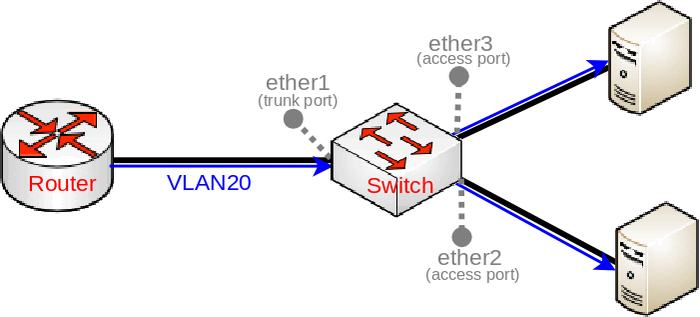
Do NOT use multiple VLAN IDs on access ports. This will unintentionally allow both VLAN20 and VLAN30 on both access ports. In the example above, ether3 is supposed to set a VLAN tag for all ingress packets to use VLAN30 (since PVID=30 ), but this does not limit the allowed VLANs on this port when VLANs are being sent out through this port. The bridge VLAN table is responsible for deciding whether a VLAN is allowed to be sent through a specific port or not. The entry above specifies that both VLAN20 and VLAN30 is allowed to be sent out through ether2 and ether3 and on top of that the entry specifies that packets should be sent out without a VLAN tag (packets are sent out as untagged packets). As a result you may create a packet leak from VLANs to ports that are not even supposed to receive such traffic, see the image below.
Warning: Don’t use more than one VLAN ID specified in a bridge VLAN table entry for access ports, you should only specify multiple VLAN IDs for trunk ports.
It is not necessary to add a bridge port as an untagged port, because each bridge port is added as an untagged port dynamically with a VLAN ID that is specified in the PVID property. This is because of a feature that automatically will add an appropriate entry in the bridge VLAN table for convenience and performance reasons, this feature does have some caveats that you must be aware of. All ports that have the same PVID will be added to a single entry for the appropriate VLAN ID as untagged ports, but note that the CPU port also has a VLAN ID.
For testing purposes we are going to enable VLAN filtering, but note that it might make you lose access to the device since it does not have a management access configured yet (we will configure it later). It is always recommended to configure VLAN filtering while using a serial console, though you can also configure a device through a port, that is not added to a bridge. Make sure you are using a serial console or connected through a different port (that is not in a bridge) and enable VLAN filtering:
Note: You might not lose access to the device as soon as you enable VLAN filtering, but you might get disconnected since the bridge must reset itself in order for VLAN filtering to take any effect, which will force you to reconnect (this is mostly relevant when using MAC-telnet). There is a chance you might be able to access your device using untagged traffic, this scenario is described below.
If you have enabled VLAN filtering now and printed out the current VLAN table, you would see such a table:
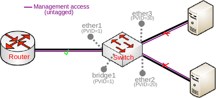
There is a dynamic entry added for VLAN1 since PVID=1 is set by default to all bridge ports (including our trunk port, ether1), but you should also notice that bridge1 interface (the CPU port) is also added dynamically. When ports are added to a single bridge VLAN table entry, the bridge can skip adding a VLAN tag and removing it when packets is being forwarded between these ports (since changing packets is not necessary and decreases the throughput), for this reason all ports with the same PVID are added as untagged ports dynamically.
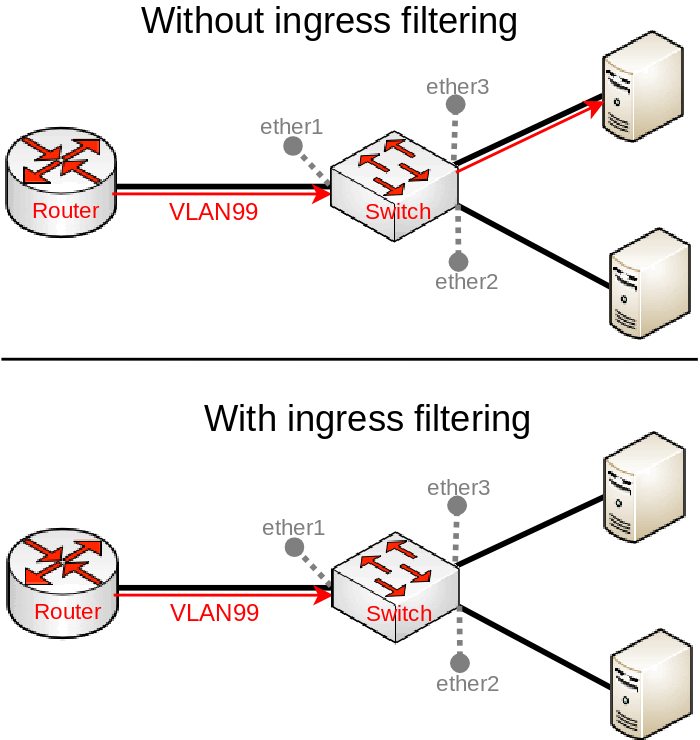
You should be aware that the CPU port (bridge1) is also a bridge port and therefore might get added to the bridge VLAN table dynamically. There is a chance that you might unintentionally allow access to the device because of this feature. For example, if you have followed this guide and left PVID=1 set for the trunk port (ether1) and did not change the PVID for the CPU port (bridge1) as well, then access through ether1 to the device using untagged traffic is allowed, this is also visible when you print out the bridge VLAN table. This scenario is illustrated in the image below:
Warning: Always check the bridge VLAN table if you have not unintentionally allowed certain VLANs or untagged traffic to specific ports, especially the CPU port (bridge).
There is a simple way to prevent the bridge (CPU port) being added as an untagged port, you can simply set the PVID on the trunk port to be different than the bridge’s PVID (or change the bridge’s PVID ), but there is another option, which is more intuitive and recommended. Since you are expecting that the trunk port is only supposed to receive tagged traffic (in this example, it should only receive VLAN20/VLAN30), but no untagged traffic, then you can use ingress-filtering along with frame-type to filter out unwanted packets, but in order to fully understand the behavior of ingress filtering, we must first understand the details of management access.
Note: You can use the feature that dynamically adds untagged ports with the same PVID value, you can simply change the PVID to match between ether3 and bridge1.
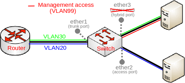
Allowing access to the device using untagged traffic is not considered as a good security practice, a much better way is to allow access to the device using a very specific VLAN sometimes called the management VLAN, in our case this is going to be VLAN99. This adds a significant layer of security since an attacker must guess the VLAN ID that is being used for management purposes and then guess the login credentials, on top of this you can even add another layer of security by allowing access to the device using only a certain IP addresses. The purpose of this guide is to provide in-depth explanation, for that reason we are adding a level of complexity to our setup to understand some possible caveats that you must take into account. We are going to allow access from an access port using tagged traffic (illustrated in the image below). In order to allow access to the device using VLAN99 from ether3, we must add a proper entry in the bridge VLAN table:
Note: If PVID for ether1 and bridge1 matches (by default, it does matches with 1), then access to the device is allowed using untagged traffic from ether1 because of the feature that dynamically adds untagged ports to the bridge VLAN table.
But you might notice that access using VLAN99 does not work at this point, this is because you need a VLAN interface that listens for tagged traffic, you can simply create this interface for the appropriate VLAN ID and you can set an IP address for the interface as well:
Note: Our access port (ether3) at this point expects tagged and untagged traffic at the same time, such a port is called a hybrid port.
Lets say that you forgot to enable ingress-filtering and change the frame-type property on ether1, this would unintentionally add access to the device through ether1 using untagged traffic since PVID matches for bridge1 and ether1, but you are expecting only tagged traffic to be able to access the device. It is possible to drop all untagged packets that are destined to the CPU port:
This does not only drop untagged packets, but this disables the feature that dynamically adds untagged ports to the bridge VLAN table. If you print out the current bridge VLAN table you would notice that bridge1 is not dynamically added as an untagged port:
Warning: Always try to use ingress-filtering wherever it is possible, it adds a significant layer of security.
The ingress-filtering can be used on the CPU port (bridge) as well, this can be used to prevent some possible attack vectors and limit the allowed VLANs that can access the CPU. It is better to drop a packet on an ingress port, rather than on an egress port, this reduces the CPU load, this is quite crucial when you are using hardware offloading with bridge VLAN filtering.
Note: The ingress-filtering property only has effect on ingress traffic, but frame-type has effect on egress and ingress traffic.
Even though you can limit the allowed VLANs and packet types on a port, it is never a good security practice to allow access to a device through access ports since an attacker could sniff packets and extract the management VLAN’s ID, you should only allow access to the device from the trunk port (ether1) since trunk ports usually have better physical security, you should remove the previous entry and allow access to the device through the port that is connected to your router (illustrated in the image below):
VLAN Tunnelling setup
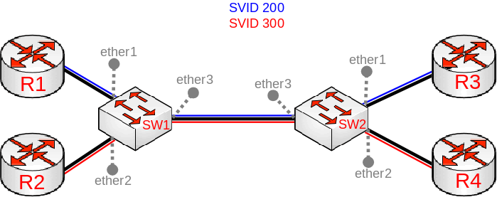
In some cases you might want to forward already tagged traffic through certain switches. This is a quite common setup for backbone infrastructures since it provides a possibility encapsulate traffic from, for example, your edge routers and seamlessly forward it over your backbone to another edge router. Below you can find an example of a VLAN tunnelling topology:
Note: To fully understand how to configure VLAN tunnelling properly, you should first read the Trunk/Access port setup section before proceeding any further.
Note: The bridge checks only the outer tag (closest to the MAC address), any other tag is ignored anywhere in bridge configuration. The bridge is not aware of the packet contents, even though there might be another VLAN tag, only the first VLAN tag is checked.
The ether-type property allows you to select the following EtherTypes for the VLAN tag:
In order to properly configure bridge VLAN filtering, you must understand how does the bridge distinguish tagged and untagged packets. Like mentioned before, the bridge will check if EtherType matches with the outer VLAN tag in the packet. For example, consider the following packet:
Both SW1 and SW2 are using the same configuration:
In this example traffic between SW1 and SW2 is going to be tagged and it will be using the SVID VLAN tag. Here we are assuming that all routers are passing traffic that is using a CVID VLAN tag and such traffic will be considered as untagged traffic based on the principle described above.
Note: All principles that applies to the regular trunk/access port setup using IEEE 802.1Q, they also apply to VLAN tunnelling setups, make sure you are limiting VLANs and packet type properly using the bridge VLAN table and ingress filtering.
In case you want to create management access from, lets say, ether3 to the device and wanted to use VLAN99, then you would use such commands:
Tag Stacking
In the VLAN Tunnelling setup we were adding a new VLAN tag that was different from the VLAN tag, but it is possible to add a new VLAN tag regardless of the packet contents. The difference between the regular VLAN tunnelling setup is that the bridge does not check if the packet is tagged or untagged, it assumes that all packets that are received on a specific port are all untagged packets and will add a new VLAN tag regardless whether a VLAN tag is present or not, this is called Tag Stacking since it «stacks» VLAN tags on top of the previous tag, regardless of the VLAN tag type. This is a very common setup for networks that do not support the IEEE 802.1ad standard, but still want to encapsulate VLAN traffic into a new VLAN.
To explain how VLAN tagging and untagging works with tag stacking, lets use the same network topology as before:
What we want to achieve is that regardless what is being received on ether2 and ether3, a new VLAN tag will be added to encapsulate the traffic that is coming from those ports. What tag-stacking does is forces a new VLAN tag, so we can use this property to achieve our desired setup. We are going to be using the same configuration as in the Trunk/Access port setup, but with tag stacking enabled on the access ports:
Lets assume that the devices behind ether2 and ether3 are sending tagged VLAN40 traffic. With this configuration ALL packets will get encapsulated with a new VLAN tag, but you must make sure that you have added the VLAN ID from the outer tag to the bridge VLAN table. The VLAN40 is not added to the bridge VLAN table since it is the inner tag and it is not checked, we are only concerned about the outer tag, which is either VLAN20 or VLAN30 depending on the port.
Similarly to other setups, the bridge VLAN table is going to be used to determine if the VLAN tag needs to be removed or not. For example, ether1 receives tagged VLAN20 packets, the bridge checks that ether2 is allowed to carry VLAN20 so it is about to send it out through ether2, but it also checks the bridge VLAN table whether the VLAN tag should be removed and since ether2 is marked as an untagged port, then the bridge will forward these packets from ether1 to ether2 without the VLAN20 VLAN tag.


